Hardware
Development Computer
The FPGA edit-compile-deploy cycle is compute and disk access intensive. Some environments (such as Xilinx Vivado) need at least 8 Gig of RAM.
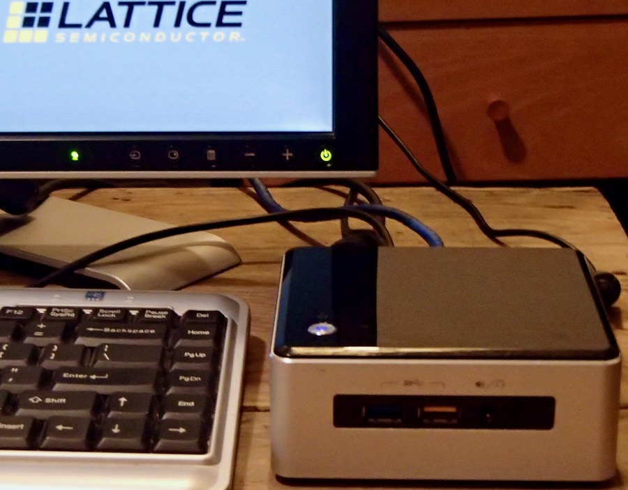
My system is an Intel NUC 5i5RYH which has an Intel Core i5-5250U Processor, clocks up to 2.7 GHz, 16 GB RAM and a solid-state drive.
I'm telling you this because you will be re-compiling, re-deploying your Verilog dozens of times, and a slow system is painful to use. In spite of my fast system, the DDS function generator we will make takes 1 min 45 s to compile, long enough to take a break, get a drink, check email...
FPGA board and I/O
Our initial projects will be built on the NandLand GoBoard.
Analog input is done using a two-channel 16 bit ADC, the Digilent Pmod AD1, with a theoretical rate of 1 million samples/second on each channel. On the GoBoard, however, that speed is not possible because its 25 MHz clock is too fast, and we have to divide it by two for the ADC to function. (The GoBoard's FPGA does not have a PLL, so dividing the clock is our only option.) We end up with 0.7 Ms/s.
Analog output is done using a one-channel 16 bit DAC, the Digilent Pmod DA3. This device can handle the GoBoard's 25 MHz clock and we get the full 1 million samples/second.
(Note: I experimented with the Digilent Pmod DA2, and was disappointed that its output becomes distorted above 250 ks/s. The data sheet doesn't clearly state this but its DAC chip isn't designed for speeds above 125 ks/s.)
To use both ADC and DAC modules at the same time, you will need a Y cable: Digilent Pmod splitter cable.
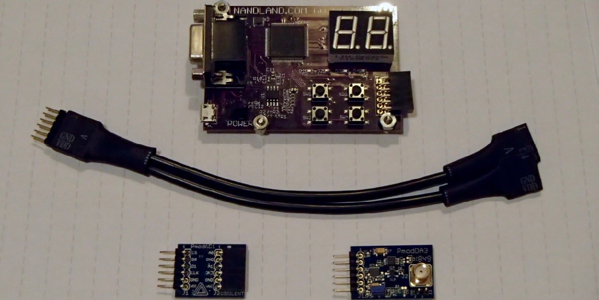

Upgrades
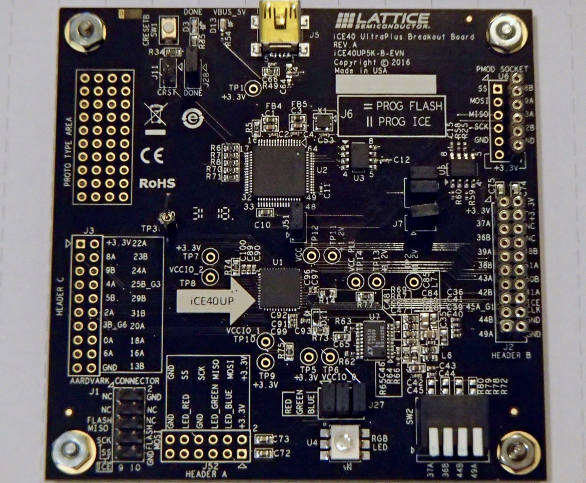
As good as it is, the GoBoard is limited. Its memory is only 16 kilobits, it has barely enough logic for the demo projects here and its clock is stuck at 25 MHz. I needed an upgrade, but I did not want to change development environments. I chose the iCE40 UltraPlus breakout board as it has 64 times more memory, can implement four times more logic (at least) and has a PLL to create adjustable clock frequencies. The downside to this board is that it is out of production. However, it is available on eBay; search for iCE40UP5K-B-EVN.
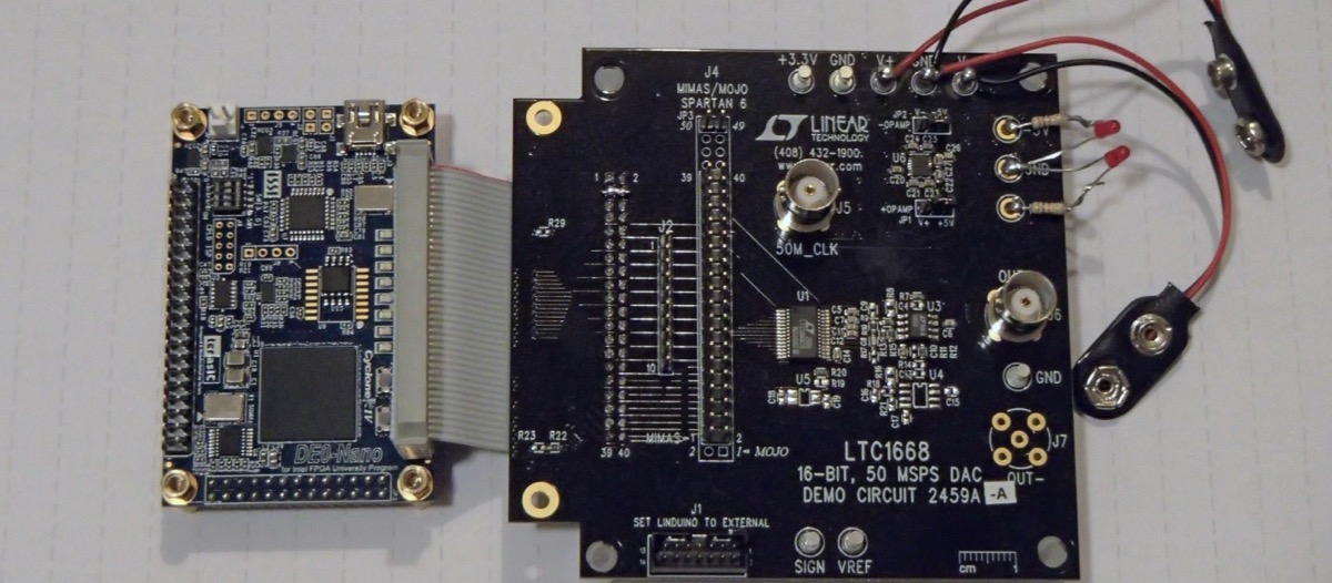
I/we do want to expand beyond the iCEcube2 software environment to Altera and Xilinx environments. (Altera has been bought by Intel.) As a step in that direction I chose the DE0-Nano board. Compared to the GoBoard this board has 34 times more memory, can implement 14 times more logic (I need to check this) and has four PLLs to create multiple adjustable clock frequencies. Development is done in the Quartus Prime environment. This board also has a 200 ks/s ADC with an 8 input analog multiplexer.
Comparison of FPGA boards used here
- Name: GoBoard
- Device: iCE40 HX1K VQ100
- Clock: 25 MHz
- PLLs(note 1): zero
- Memory: 16 kbits
- Logic Cells: 1280
- PLBs(note 2): 160
- DSPs(note 3): zero
(1) PLLs, Phase-Locked Loops are mainly used to get different clock frequencies.
(2) PLBs, Programmable Logic Blocks are the resource that runs out first.
(3) DSPs, Digital Signal Processors, are combinations of multipliers and adders that can replace a large number of programmable logic blocks.
- Name: iCE40 UltraPlus breakout board
- Device: iCE40UP 5K SG48
- Clock(note 1): 12 MHz
- PLLs: 1
- Memory: 1024 kbits
- Logic Cells: 5280
- PLBs: 660
- DSPs: 8
(1) The 12 MHz clock can be changed via the PLL. Additionally, there is a 10 kHz and a 48 MHz clock but these are low-accuracy oscillators not necessarily suitable for laboratory work.
- Name: dE0-nano
- Device: Cyclone IV EP4CE22F17C6N
- Clock: 50 MHz
- PLLs: 4
- Memory: 549 kbits
- PLBs (note 1): 22320
- DSPs (note 2): 66
(1) This is the number of "Logic Elements". I'm not sure how to compare to Lattice.
(2) This is the number of 18x18 bit multipliers, which are an essential part of DSPs.
Test equipment
You're not going to get much done without these tools: oscilloscope, function generator and an audio amplifier.
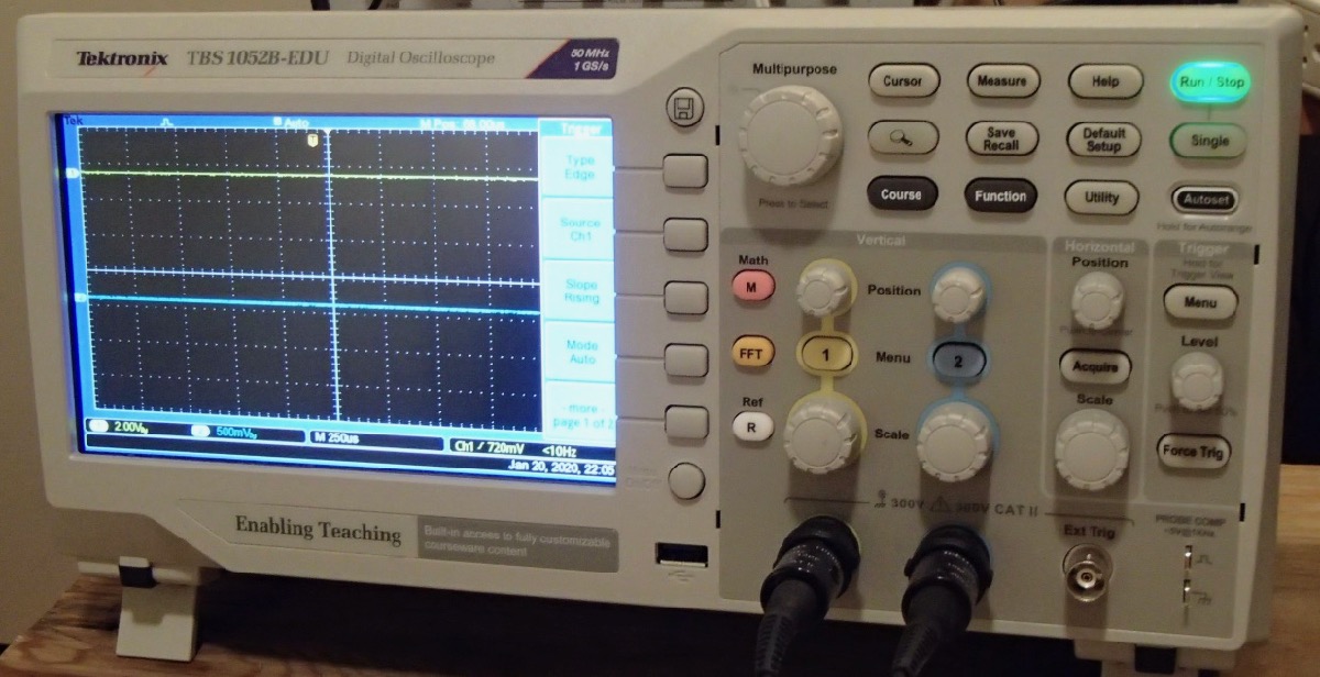
Digital Oscilloscopes are great for their steady, bright display, especially for single events. BUT, they can be "fooled" by aliasing, a significant problem when troubleshooting mixed digital/analog systems.
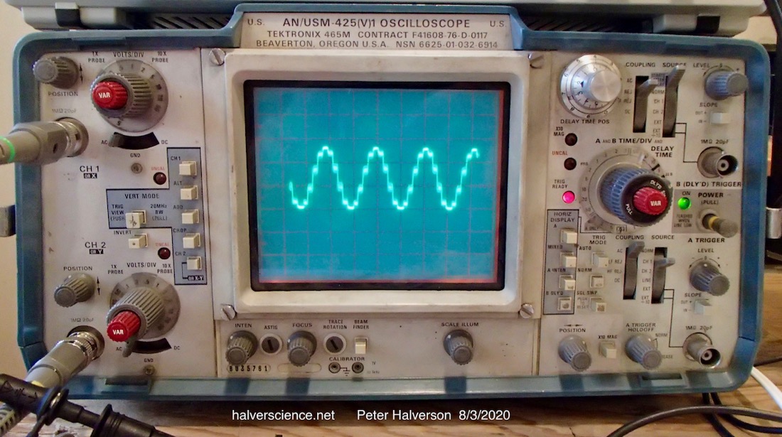
Analog Oscilloscopes are good "truth checkers." The display isn't as bright and clear but analog scopes aren't fooled by aliasing. We will explore this issue in the Analog Output section of this site. High quality analog oscilloscopes are available used, at low cost on eBay.
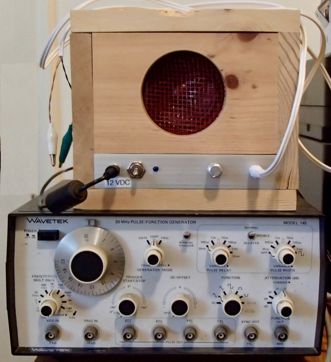
Signal or Function generators are needed to feed stable test signals to ADCs.
Audio Amplifier & Speaker can hear what is going on. Listening to the FPGA's output is fun and often reveals bugs you might otherwise miss.
